2.2 Problem Solving and Design with UML
Introduction
UML (Unified Modeling Language) is a standardized, general-purpose diagraming techniques designed for the field of Software Engineering. UML contains sets of graphic notations for modeling object oriented code and databases.
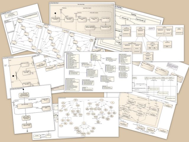
UML diagrams are used extensively in the Analysis and Design phase in the Software Development Life Cycle (SDLC), allowing a software solution to be visualized as a set of diagrams for discussion and review before any code is written. The diagrams also are useful where software is written in teams of developers, where each developer needs to understand the planned technical implementation.
There are a number of UML Diagrams, however, in this section we will consider a subset of the available diagrams in the specification. For more information, you can refer to the UML.org website.

Class Diagram
A class diagram describes the structure of a system by visualizing the classes, their attributes and their functions, as well as the relationship between the classes of that system. The Class Diagram is the fundamental diagramming tool in Object-orientation, and is used both for conceptual modeling, as well as for detailed specification.
Classes
Each class is described as a block with three vertical compartments.

- The name of the class is found in the top section.
- The attribute list is in the middle section.
- The functions list is in the bottom section.
Visibility can be specified on both the attributes as well as the functions with the following prefixes:
"+"       Public
"-"       Private
"#"       Protected
"_"       Static
"~"       Package
Relationships
Relationships between the classes are noted by annotated connecting lines between the classes.
Association
When two classes are linked by association (for example a subscriber is subscribed to a magazine), then we use the following notation:

Composition
To denote one or more classes making up a composite class, we use the following notation:

Inheritance
To denote specialization of child classes, inheriting from a generalized class, we use the following notation:

Use Case Diagram
The second UML diagram we will look at is the Use Case diagram. This is used in modeling the various user roles, and what functionality each role will use and have access to. The diagram is made up of the system's functional components, contained within the system boundary, with the actors or user roles surrounding the system boundary. To indicate the access of system functionality by the actors, there are lines connecting the various roles to the functionality they each will make use of within the system.

Sequence Diagram
Sequence Diagrams model the interaction of processes, constructed as a Message Sequence Chart, where object interactions are arranged in time sequence. It depicts the objects and classes involved in functional scenarios identified by the Use Case diagram, showing the sequence of messages exchanged between the objects needed to carry out the functionality of the scenario.
The diagram is comprised of parallel vertical lines, referred to as lifelines. The various processes and objects involved which live simultaneously are depicted as vertical boxes, and the messages exchanged between the processes are denoted by horizontal arrows.

Exercises
- Draw a class diagram for the Animals example in the section on Abstraction.
- Draw a class diagram for the Car example in the section on Composition.
- Draw a Use Case diagram for this P2PU course, depicting a course organizer, course participant, and a guest user (not signed up for the course).
- Draw a Sequence Diagram for requesting a website address in a web browser.