3.1 Introduction to Databases
Tables
In organisations, within communities, and in our private lives, data and the management thereof is of paramount importance. As developers, we are tasked with managing, manipulating, validating, securing and analysing data in complex ways whilst at the same time making such tasks simple for users to perform, thus giving the client greater power over their data.
At a very basic level, the majority of business information systems have the following data flow:
Capture Raw Data => Store Data => Manipulate => Reports
End users have been using tools such as spreadsheets to accomplish this for decades. A spreadsheet (such as those built with Microsoft Excel) is a simple table structure with rows and columns. An example of such a structure is as follows:
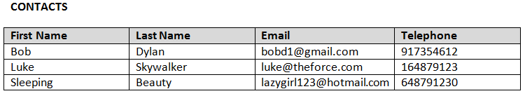
We can see that the two axis or dimensions of a table structure are:
- Columns: attributes or properties common to all items listed in the table. Columns are also referred to as fields.
- Rows: each row represents a unique item, entity or object (or contact as in the above example) in the table.
Now that we understand the concept of a table, we can now start to discuss the concept of a database.
Database Structures
A database is simply a collection of tables. The purpose of this is to group tables of data into conceptual collections of tables. For example, you might have one database per application that you write. In some other situations, you might have a single database for an organisation with multiple applications using that data.
An example would be a simple task management application. A database might be created for the application with tables such as users, queues, and tasks. The users table would contain usernames and passwords for users of this application. The queues table might contain task queues, for example, ‘Technical Support’, ‘Project Management’, ‘Management’, ‘Internal’, etc. Finally, the tasks table would contain the details of the particular task, such as the User that is assigned the task, the Queue that the task belongs to, the Due Date and the tasks Description.
Before any code gets written for an application, it is of the utmost importance to first have a solid understanding of the different types of data you will be working with, secondly the attributes of those types of data and thirdly the relationships between the types of data (also known as entities).
Entity Relationships
When designing a database structure, we add in special fields to the various tables to allow us to track the relationships between the tables (or entities) in a database. So, in the above example, instead of storing lots of pieces of information about the responsible user and queue to which a task belongs all in the tasks table, we simply store a single reference field in the tasks table to a unique field in the users table, and similarly for the queue, we store a reference field in the tasks table to a unique field in the queues table. So, for example:
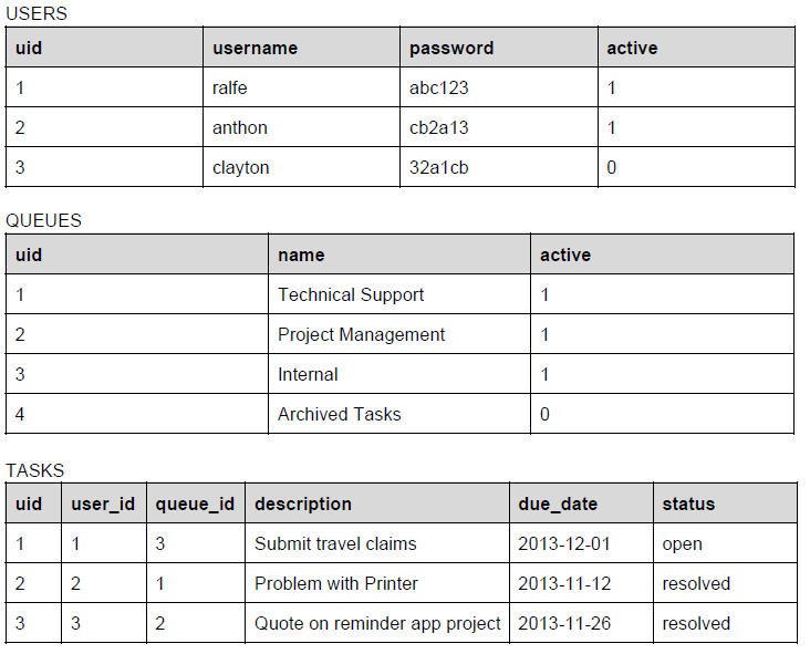
From the above example tables, we see in the users, queues and tasks tables, they each have a uid field. This stands for Unique IDentifier, and is a unique field in each of the tables, which means that if we wanted to refer to a single, specific row in a table without worrying about ambiguity, we would use this unique identifier. The unique field in a table is referred to in software development terminology as the PRIMARY KEY.
We can think of the primary key as the most important means of identification for a row in a table. An analogy would be the ID number of a person in a country. In each country, the individual people are uniquely identified, not by names (which are not necessarily unique to a person), but rather by a uniquely generated and assigned identification number. So too in a database, the database engine will often automatically generate the unique identification number for the row at the time that the row is first inserted into the table.
Once we have a primary key set for a table, we can use it in another table to reference particular rows in the originating table. We refer to these fields which reference PRIMARY KEY's as FOREIGN KEYS. For example, in the tasks table, we have a user_id and a queue_id field. These will each refer to rows in the users and queues table respectively by quoting the relevant primary key values. Thus, in row 1 of the tasks table, the user that is associated to that task is user 1, which is ralfe, and the queue to which the tasks belongs is queue 3, which is Internal. Additionally, in row 2 of the tasks table, the associated user is user 2, which is anthon, and the queue is queue 1, which is Technical Support.
The basic rule of thumb is that a FOREIGN KEY in one table refers to the values in the PRIMARY KEY of another table. Due to PUBLIC/FOREIGN KEY relationships, it is almost never necessary to duplicate information stored in one table into another table beyond the value of the public key field. As soon as you break this principle, you open the way for data anomalies. For example, if you had stored the name of the queue that a task belongs to in the tasks table, then there could potentially be an update anomaly if you change the name of the queue in the queues table, but did not update the name of the queue in the tasks table. However, if you had simply had a foreign key reference to the public key of the queue, then you could change the name of the queue in a single place, and not have to worry about data anomalies.
Another aspect to entity relationships is the type of relationship between the primary and foreign key.
One-to-one Entity Relationships
This occurs when one row in the first table is linked to one row in the second. This kind of relationship is possible, but rarely used. If you find yourself designing a database structure with a one-to-one entity relationship, you should stop and consider why you have not simply combined the fields in the two tables into a single table/entity?
One-to-many Entity Relationship
This is a very commonly occurring entity relationship. In our above example, there are two one-to-many relationships. The first one is between users and tasks, and the second is between queues and tasks. This relationship can be described through the following UML (Unified Modelling Language) diagram:
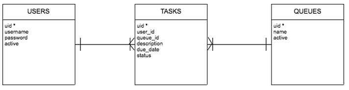
The above diagram is a type of diagram known as an ERD (Entity Relationship Diagram). This type of diagram allows us to specify the entities, their attributes, and the relationships between the entities. In an ERD, the entity names correspond to table names, their attributes are the fields in the table, and the links between them specify the nature of the primary-foreign key relationship.
In this example, we see that one user, may have many tasks assigned to them. Similarly, one queue will contain multiple tasks. However, we see that one task cannot belong to multiple queues, and cannot be assigned to multiple users.
Many-to-many Entity Relationship
Often, you will come accross a situation where a table's rows will belong to many rows in a second table, and the rows in the second table can belong to multiple rows in the first. For example, if you had two entities, classes and students; one student can take multiple classes, and one class can accommodate multiple students. Now, we have a problem because we can’t simply have an indefinite number of fields to hold the various foreign keys we would need. This would be both impractical and technically complex.
The solution is to add in an additional entity which sits in between the two entities for which a many-to-many relationship exists. This additional entity is a special type of entity called an associative entity. For each pairing of records between the two tables, a single record will exist in the associative entity. So, for example, with our classroom example above, we might have an associative entity called registrations, which would look as follows:
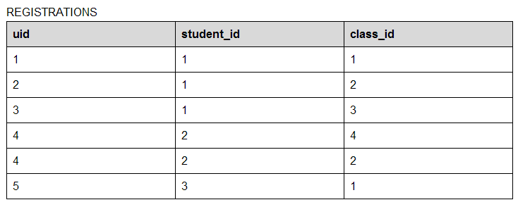
So, with this table, we see that there is a public key, as per usual, and then just the two foreign keys which we are linking so as to allow for the many-to-many relationship. Thus, student 1 is attending classes 1, 2, and 3. In addition, we can see that class 2 is being attended by student 1 and 2, whereas class 3 is being attended by all three students.
Exercises
- Explain the problem with having data (other than the primary key) duplicated in more than one table for a single item.
- What is the purpose of an associative entity?
- Give three real-world examples of where you would modal data using a many-to-many relationship.
- What is the difference between a PRIMARY and FOREIGN key?